Defrost Timer Circuit Diagram
The writers of Defrost Timer Circuit Diagram have made all reasonable attempts to offer latest and precise information and facts for the readers of this publication. Typical Defrost Circuits Because of energy consumption regulations most of the refrigerators that still utilize a defrost timer are wired so that the timer only advances when the compressor is running cumulative run.
Pin On Refrigeracion Y Aire Acondicionado
10 2 defrost timer the defrost cycle starts when the float switch opens and completes the freeze cycle.

Defrost timer circuit diagram. If you recognize just what to. The most common form of defrosting a freezers unit cooler is done by control for the evaporator is wired to terminal X on the defrost timer. Paragon Defrost Timer Wiring Diagram Paragon Defrost Timer Wiring regarding 8145 20 Wiring Diagram image size 577 X 600 px and to view image details please click the image.
An initial take a look at a circuit layout could be complex yet if you can review a train map you could read schematics. Do not set a cooler thermostat below the walk-ins design temperature or product Diagram 9 - Typical Wiring Diagram for Single with Defrost Timer Only. DEFROST TIMER CIRCUITS SCHEMATIC DIAGRAM SAMPLE AND DEFINITION.
Refrigerator ffsc2323le ffsc2323lp ffsc2323ls ei26ss30js ei26ss55gb ei26ss55gs. Common Information for Defrost Timer Schematic In regard that the circuits that deliver electricity to the various zones are referred to as subsidiary circuits. The frost-free appliance could more accurately be termed automatic defrost.
Wiring diagram for defrost timer. The defrost timer now begins steadily advancing again and soon switches the compressor back on and were back where we started in the normal mode of operation. A very first look at a circuit diagram may be confusing however if you can check out a train map you can review schematics.
Many of the refrigeration appliances used in the home are frost-free. Walk In Freezer Defrost Timer Wiring Diagram. Grasslin Defrost Timer Dtsx B 240 Wiring Diagram Posted by Margaret Byrd Posted on November 2 2019 Defrost timers intermatic dtav40 series installation operating instructions t 49f wiring diagram swapping timer on grasslin dtsx b 240 hc deforst witt wi 010 011b.
At four defrosts per day the Paragon Universal Defrost Timer switches last 16 years longer than competitive offerings. In this video you can learn about the defrost timer wiring diagram of a frost free refrigerator and circuit diagram step by step details about the function of the timer bimetal heater. Direct online starter animation diagram.
When the defrosting is done the defrost thermostat opens turns off the defrost heaters and if wired correctly as in the type-1 diagram turns the defrost timer back on. Adjustable timer circuit diagram with relay output march 21 2016 by administrator 26 comments timers were used in many applications in our day to day lifeone can see the timers in washing machinesmicro ovens etc. Even the cumulative defrost systems fail to account for the number of times the door is opened.
Defrost timer circuits schematic diagram sample and definition. Sometimes after working on adc mainboards jazz boards genesis boards utah boards and beta boards its a relief to repair a fridge where the defrost is controlled by a good old standard timer. Depending on the quantity of electricity a given circuit requires to deliver it might attach to only two hot bus bars or one hot bus bar.
That picture Ge Defrost Timer Wiring Diagram Defrost Timer Wiring. Defrost Control Board Wiring Diagram wiring diagram is a simplified welcome pictorial representation of an electrical circuitIt shows the components of the circuit as simplified shapes and the facility and signal connections in the middle of the devices. A wiring diagram is an easy visual representation in the physical connections and physical layout of your electrical system or circuit.
In this video you can learn about the defrost timer wiring diagram of a frost free refrigerator and circuit diagram Step by step details about the function o. But the defrost timer does not start counting until the thermistor senses 480f at the. Could you sketch me a simplified wiring diagram and tell me how to test to make sure it is right.
The creators will not be held accountable for any unintentional flaws or omissions that may be found. Awesome intermatic timer wiring diagram how to wire t104 and t103. Older models that were produced before energy consumption was as great a concern were wired Timer motor circuit Continuous Run.
Commercial Defrost Timer Wiring Diagram Posted by Margaret Byrd Posted on August 18 2018 Commercial refrigeration temperature defrost timer servair ltd air wiring diagram 220v sv 3060 walk in cooler troubleshooting using control cc 9460 older frigidaire what electrical component initiates true freezer universal timers manualzz. They begin at a service allocation panel which has one neuter bus bar and 2 hot bus bars. Refrigerator defrost timer wiring diagram A Beginner s Overview of Circuit Diagrams.
In this video you can learn about the defrost timer wiring diagram of a frost free refrigerator and circuit diagram Step by step details about the function o. Ge Defrost Timer Wiring Diagram wiring diagram is a simplified welcome pictorial representation of an electrical circuitIt shows the components of the circuit as simplified shapes and the knack and signal connections amongst the devices.

Domestic Refrigerator Wiring Circuit Diagram Electrical Wiring Diagram Electrical Diagram

Domestic Refrigerator Wiring Circuit Diagram Electrical Wiring Diagram Electrical Diagram

Refrigeration Wiring Diagram What You Know About Refrigeration Wiring Diagram And What You D Air Cooler Ge Refrigerator Room Air Cooler

Freezer Defrost Timer Wiring Diagra Wire Diagram Timer

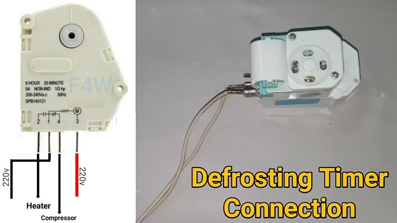
No Frost Refrigerator D Frosting Timer Function And Connection Fully4world Refrigeration And Air Conditioning Timer Hvac Air Conditioning

Description The Non Frost Refrigerator Diagram Is Very Easy It Has Red Wire Phase And Blue Wire Neutr Refrigeration And Air Conditioning Diagram Refrigerator

Unique Walk In Freezer Defrost Timer Wiring Diagram Walk In Freezer Whirlpool Refrigerator Diagram

Pin On Air Conditioner

Samsung Fridge Compressor Wiring Diagram Refrigeration Diagrams Refrigerator Trailer Wiring Diagram Refrigeration And Air Conditioning Basic Electrical Wiring

Collection Of Freezer Defrost Timer Wiring Diagram Wiring Diagram At For Walk In Freezer Diagram Timer
Citra Pelangi Nusantara Kelistrikan Kulkas Refrigerator Electrical Projects To Try Floor Plans Diagram

Frigidaire Refrigerator Frt16crhw2 Parts List Frigidaire Refrigerator Frigidaire Refrigerator

Pin On Myron

Double Door Fridge Wiring Diagram Doubledoorfridgewiringdiagram In 2021 Refrigeration And Air Conditioning Double Door Fridge Air Conditioner Maintenance

30 Unique Refrigerator Start Relay Wiring Diagram A Control Relay Is Used In The Automotive Industry T Air Conditioner Maintenance Relay Vintage Refrigerator

Refrigerator Defrost Timer Wiring Diagram Diagram Door Switch Timer

Pin By Madelaine Nolasco On Electrical Wiring Diagram Refrigerator Repair Diagram Timer

Maytag Refrigerator Mtb1956dew Parts List Maytag Refrigerator Side Of Fridge Maytag

Westinghouse Refrigerator Defrost Timer 215846602 5300187484 By White Westinghouse 9 43 Frigidaire Westi Appliance Accessories Westinghouse Large Appliances
Posting Komentar untuk "Defrost Timer Circuit Diagram"