Franklin Well Pump Wiring Diagram
Here is the complete guide step by step. The manual will contain important safety precautions wiring diagrams tools required for assembly proper grounding.

Aim Manual Page 55 Single Phase Motors And Controls Motor Maintenance North America Water Franklin Electric
Call franklin toll free 800-348-2420 for information.

Franklin well pump wiring diagram. In this video I go over the differences of a 2 wire and a 3 wire submersible well pumpThis is associated with the starting components for the pump and whet. This refers to a european sizing that is measured in millimeter squared mm2. Technicians should test a well pumps control box before pulling a nonworking pump from the well.
Many thanks for visiting our website to search Franklin Submersible Pump Wiring Diagram. Do not allow pump or any system plumbing to freeze. Franklin Electric Well Pump Control Box Wiring Diagram wiring diagram is a simplified standard pictorial representation of an electrical circuitIt shows the components of the circuit as simplified shapes and the capability and signal connections with the devices.
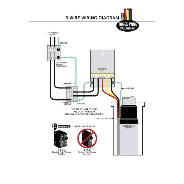
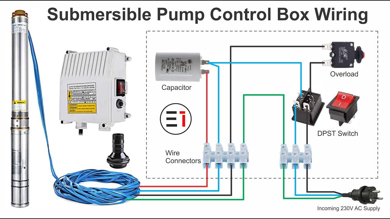
Single-phase submersible pump control box wiring diagram - 3 wire submersible pump wiring diagram. Franklin electric 1 to 1 1 2 hp pump control box internal parts submersible pumping systems pdf document 3 4 hp franklin electric submersible water well pump wet end goulds j10 1 hp convertible water well jet pump 115 230v 1ph product catalog fr 0652 3 phase pump wiring wiring diagram product catalog cheap pompa submersible deep well find pompa submersible product. GB SubDrive750050 Constant Pressure Controller Installation Manual Contents Controller Model Franklin Electric Motor Model Rated Power KW HP5.
Our website uses cookies for analytics and to enable dynamic contentLearn More. Franklin Well Pump Wiring Diagram Schematics Wiring Diagram 240 Volt Well Pump Wiring Diagram Uploaded by Hadir on Saturday February 9th 2019 in category Wiring Diagram. Wiring diagram franklin electric control box.
Hopefully we provide this is often ideal for you. The wiring connection of the submersible pump control box is very simple. Well pump pressure switch wiring diagram Square D Well Pump Pressure Switch Wiring Diagram.
Keep work area clean well-lit and uncluttered. Starter wiring diagram box 2wire well pump diagram mentri he 3944 water pump wiring diagrams 230v wiring diagram submersible motors. The diagrams for both the two and three wire pumps can be downloaded using Adobe.
1 - hp Date Codes 11C19 Newer. Before getting started look up your owners manual and read over the precautions and all other warnings before beginning the installation. The green ground wire should also be terminated to the box and a ground coming from the panel.
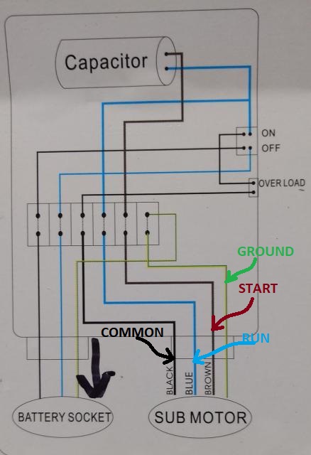
Visually inspect the control panels wires wire connections relay and capacitor Connections loose See wiring diagram or misconnected in in control box. At 1426 the ship was attacked by japanese planes. It is designed to work on any 230 VAC single.
In the submersible pump control box we use a capacitor a resit-able thermal overload and a DPST switch double pole single throw. Protection Features Dry Well Underload Over Under Voltage Rapid Cycle Bound Pump Indicator Lights Load Voltage Status Other Features. Pumptec is optimized to work with Franklin 2- and 3-wire single-phase motors from 13 to 15 hp.
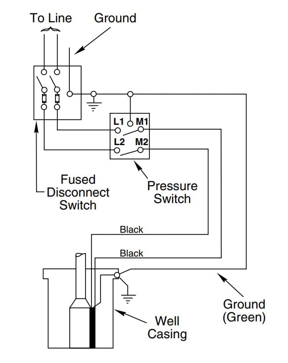
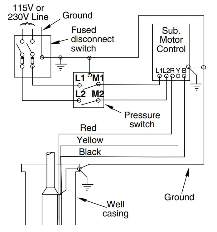
Pumptec-Plus is the most sophisticated pump protection system on market today. Shows a typical wiring diagram for a 2-wire installation. READ Bulldog Security Alarm Wiring Diagram Collection.
Our library is the biggest of these that have literally hundreds of thousands of different products represented. Wiring Diagram Sheets Detail. Franklin Electric Pump Controller Model 2823 Wiring Diagram.
The number wire size varies from 05 to 60. This reduced diameter pump end makes it ideal for installations where the well is considered encrusted or tight in comparison to a standard 4 well. The Franklin Electric C1-Series cistern pumping system is designed and approved for use in effluent pumping applications.
Well pump installation can be dangerous when dealing with water and electricity so extreme caution must be taken. After determining the voltage is zero disconnect the motor wires directly from the pressure switch box M1 and M2. An underload dry well adjustment is provided to address unusual situations.
Well pumps with control boxes have start and run circuits. Control Box Wiring Diagrams. Franklin installation information is available from pump manufacturers and distributors and directly from franklin electric.
To replace the two wire pump. Please see more wiring amber you can see it in the gallery below. See also 220 Pump Wire Diagram Wiring Library 240 Volt Well Pump Wiring Diagram from Wiring Diagram Topic.
Control Box Wiring Diagrams Continued. Here we have another image 240V Well Pump Wiring Diagram Pressure Switch Manual E. Gemini gem rp1cae2 gemini gem k1ca.
To get started finding Franklin Electric Well Pump Control Box Wiring Diagram you are right to find our website which has a comprehensive collection of manuals listed. 1 - hp Date Codes 11C19 Older. Local electrical codes and within franklin electric recommendations may result in electrical shock or fire hazard unsatisfactory performance and equipment failure.
The 3200 Series submersible pumps are designed so that all parts of the pump end including the cable guard fall within the diameter of Franklin Electrics industry leading submersible 4 motor. The kit comes with two installation screws and the element.
How To Install And Wire A Well Pump Well Pump Installation Guide
Eco Flo 1 Hp Control Box For 4 In Well Pump Efcb10 Hd The Home Depot

Aim Manual Page 54 Single Phase Motors And Controls Motor Maintenance North America Water Franklin Electric

Aim Manual Page 54 Single Phase Motors And Controls Motor Maintenance North America Water Franklin Electric

44 Luxury Single Phase Submersible Pump Starter Wiring Diagram Well Pump Submersible Well Pump Submersible Pump

Aim Manual Page 54 Single Phase Motors And Controls Motor Maintenance North America Water Franklin Electric
Water Pump Wiring Troubleshooting Repair Pump Wiring Diagrams
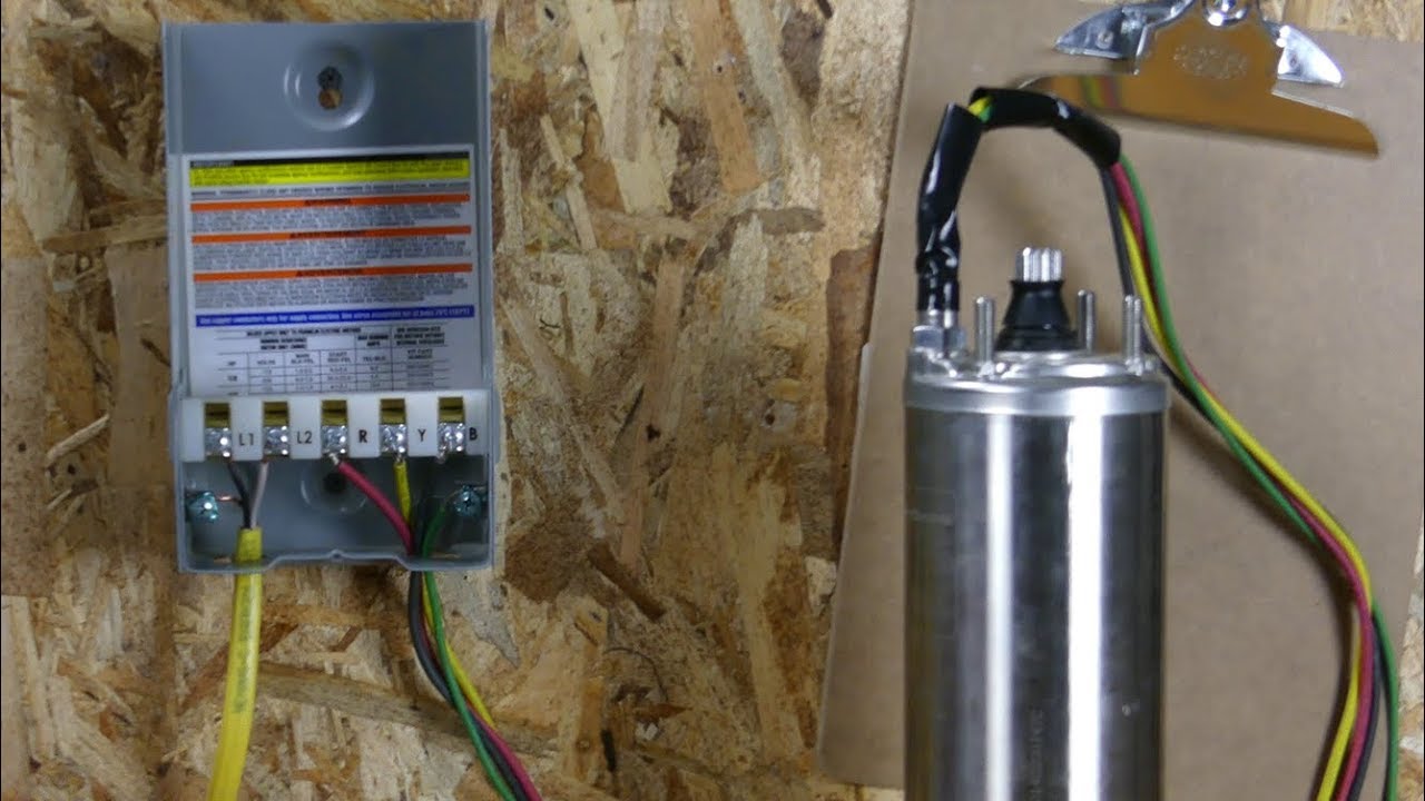
How To Wire A Franklin Electric Qd Control Box 1 3 1 Hp Youtube

Wiring Diagram For 220 Volt Submersible Pump Submersible Pump Awesome Wiring Diagram For Motorcycle Haz Submersible Pump Sump Pump Electrical Circuit Diagram

Aim Manual Page 54 Single Phase Motors And Controls Motor Maintenance North America Water Franklin Electric
How To Wire Submersible Motor Control Box By Elektricar 1 Youtube

Diagram Wiring Diagram For Control Box Well Pump Full Version Hd Quality Well Pump Jdiagram Antichemurasorrento It

Submersible Pump Control Box Wiring Diagram For 3 Wire Single Phase Submersible Pump Submersible Well Pump Well Pump
How To Install And Wire A Well Pump Well Pump Installation Guide

Submersible Water Pump Control Box Wiring Diagram Youtube
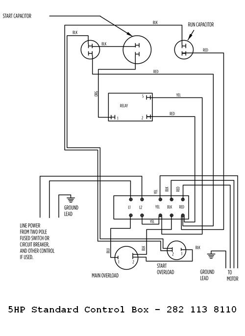
Diagram 5 Hp Well Pump Control Box Wiring Diagram Full Version Hd Quality Wiring Diagram Solardiagrams Hotelrigelcatania It

Submersible Motor Control Box Wiring Single Phase Water Pump Water Pump Youtube
Submersible Water Pump Control Box Wiring Diagram Youtube

Diagram Deep Well Pump Wiring Diagram Full Version Hd Quality Wiring Diagram Circutdiagram Hotelrigelcatania It
Posting Komentar untuk "Franklin Well Pump Wiring Diagram"